[Preorders Open] Plug N' Play Upfitter Wiring Harness

Cblaxx19

Well-known member
Tremor of the Month
Joined
Mar 4, 2022
Messages
929
Reaction score
1,825
Location
Jupiter
Current Ride
‘21 Leadfoot Grey 402A Tremor
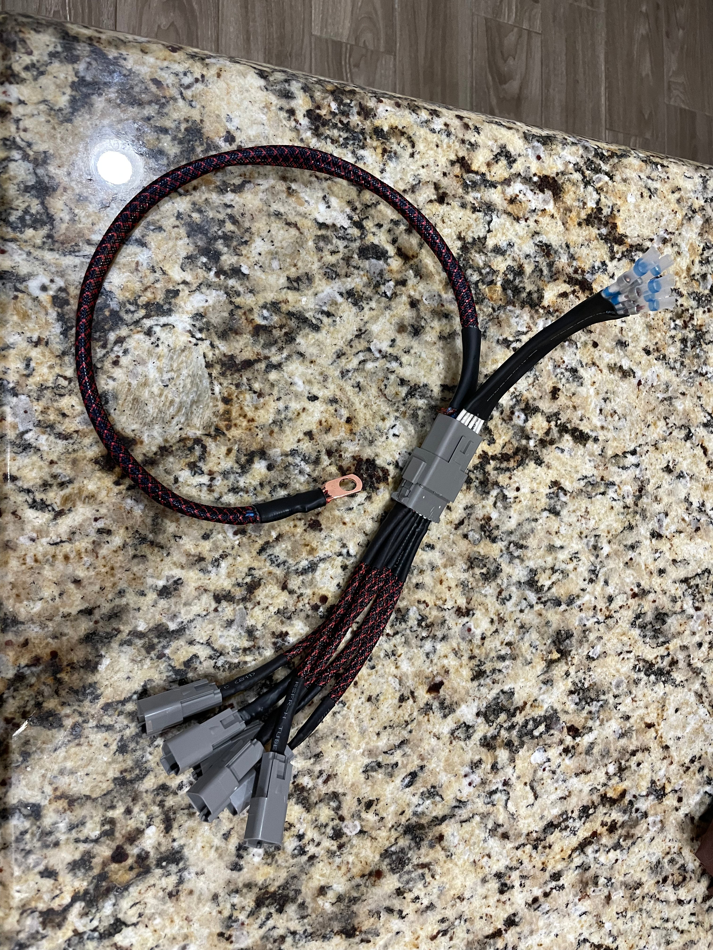
In Collaboration with @beo_tom , would there be interest in a plug n' Play harness for the upfitters? This harness would easily tie into the 6 upfitter wires provided from the Factory and convert those 6 wires into 6 x 2 pin(power and ground) water proof deutch connectors.

Pricing for the harness would be $100 plus shipping

Tools required for install:
Wire strippers to expose wire on factory upfitter wiring
Heat gun/hair dryer/lighter to shrink shrink tubing
adjustable wrench to install ground leads onto Battery negative terminal


The harness would come with solder shrink waterproof butt connectors already installed on the upfitter leads. User would only need a heat gun/lighter to shrink the other side down on to the upfitter wires from the truck and melt the solder to securely splice the upfitter wires to the harness.

Then the ground terminal would go to the negative terminal of the battery.

Included would be 6 x 2 pin male connectors pre wired with ~6" of wire for the user to splice to their desired accessory, assuming it doesn't come with a 2 pin deutch connector already on it.

Preorder page open. https://cblightingdesigns.myshopify.com/products/upfitter-wiring-harness
cblightingdesigns.myshopify.com

Upfitter Wiring Harness

This is a preorder in order to determine the correct order quantities for materials. Material orders will be placed on November 24th based on harness orders. Lead time would then be 4-6 weeks after that. Turn the short, poorly placed, hard to get to factory upfitter wires into easy to access...
cblightingdesigns.myshopify.com

Will take orders till the 24th and them
Place material orders. Lead time for delivery is 4-6 weeks from the 24th.

We will shoot for earlier if we can.

This is a sample harness:

IMG_9316.jpg


IMG_9315.jpg


IMG_9314.jpg


IMG_9313.jpg


Instal pictures from @beo_tom
IMG_9324.png


IMG_9325.png


IMG_9323.png


Credit for the harness idea goes to @beo_tom. he recently shared his upfitter harness that he created for his truck and there was interest in it from other members. He mentioned possibly collaborating with me on making them for folks so i reached out to him and we have been working on refining the harness design, creating the parts list, and working out pricing.
 
Last edited:
That's a cool idea. I ended up putting single weather pak connectors on my ends- that way when I decide I want to change what switch a circuit is on, easy to swap around. Same idea but didn't cost but a few cents. No ground provisions though.
 
That's a cool idea. I ended up putting single weather pak connectors on my ends- that way when I decide I want to change what switch a circuit is on, easy to swap around. Same idea but didn't cost but a few cents. No ground provisions though.
That’s fair. We fully understand that there are plenty of people On here with the tools,knowledge, and willingness to do something like that themselves. This is really for those who don’t want to source the parts and certain tools to pin out connectors like this. They need minimal tooling and it’s a well made harness.

Appreciate the feedback though.
This would be me with electrical. I can install all the mechanical parts, but my brain goes dead at finding the different parts to make electrical work. I'd be in for one
 
This would be me with electrical. I can install all the mechanical parts, but my brain goes dead at finding the different parts to make electrical work. I'd be in for one
This really makes it simple. very little thinking required!
 
Very cool idea not to mention a time saver.
 
I will buy one!
 
I’d be down for one. One suggestion though would be to label the amps as well as the switch number.
Yea, in the pictures on my truck I have it numbered. @Cblaxx19 made a good point that a 6 amp accessory on a 5 amp fuse would blow the circuit so numbering is a good idea
 
Comfortable with electrical, but I’d still be in for one to get it rolling,
 
if every switch is on and at is maximum load can the big plug handle it at 100% duty cycle? Or just for relay use? I think it’s a great idea and the Raptor guys will love it. I think I will do something using the block to make it even cleaner.

IMG_0078.jpeg
 
if every switch is on and at is maximum load can the big plug handle it at 100% duty cycle? Or just for relay use? I think it’s a great idea and the Raptor guys will love it. I think I will do something using the block to make it even cleaner.
Do you mean the 12 Pin? or do you mean the negative lead to the battery?

Each pin is independent of each other, and 16ga wire is good for roughly 20 amps in a 12vdc chassis scenario (10ft). I think we technically could have gotten away with 18ga because the max anticipated current one of these pins would face is 15amps, but thats a little too close for comfort.
 
if every switch is on and at is maximum load can the big plug handle it at 100% duty cycle? Or just for relay use? I think it’s a great idea and the Raptor guys will love it. I think I will do something using the block to make it even cleaner.

View attachment 24134
that distribution block isn't 6 separate circuits. 2 of the ports are inputs that then get split into 2 outputs each.
1699546837401.png


relative to your question regarding the 12 pin connector handling all 6 circuits on at once. that's a good question and something I'm gonna look into further. initial spec sheet data for the connector states 13 amps as the max current. i feel like there is something i don't understand about the ratings though since the connector is designed to take 12 14-18ga leads(or 6 pairs as in this case). that would lead one to believe that it should be able to handle the current rating of the wire it is housing. even one 14 ga wire at 0-4 ft in length can handle 15amps at 13.8v according to this table(https://www.offroaders.com/technical/12-volt-wiring-tech-gauge-to-amps/). so that would say that the 12 pin connector could barely handle just one lead that it is designed to carry.

the other thing that doesn't add up is that the upfitter wires themselves are 18ga max, and shouldn't even be an option for wire size for any of the upfitters.

so there is something that i'm missing in what really dictates the necessary gauge wire as well as how the connectors are rated. if you know the secret mathing involved in any of these, i'd love to learn.
 
that distribution block isn't 6 separate circuits. 2 of the ports are inputs that then get split into 2 outputs each.
View attachment 24135

relative to your question regarding the 12 pin connector handling all 6 circuits on at once. that's a good question and something I'm gonna look into further. initial spec sheet data for the connector states 13 amps as the max current. i feel like there is something i don't understand about the ratings though since the connector is designed to take 12 14-18ga leads(or 6 pairs as in this case). that would lead one to believe that it should be able to handle the current rating of the wire it is housing. even one 14 ga wire at 0-4 ft in length can handle 15amps at 13.8v according to this table(https://www.offroaders.com/technical/12-volt-wiring-tech-gauge-to-amps/). so that would say that the 12 pin connector could barely handle just one lead that it is designed to carry.

the other thing that doesn't add up is that the upfitter wires themselves are 18ga max, and shouldn't even be an option for wire size for any of the upfitters.

so there is something that i'm missing in what really dictates the necessary gauge wire as well as how the connectors are rated. if you know the secret mathing involved in any of these, i'd love to learn.
I always used this chart when looking up sizes


Seems to be some conflict there. both charts claim to be for automotive applications
 

New Topics

Back
Top