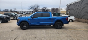
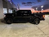
Custom Third Brake Light/Chase light

It’s common on euro vehicles to have a “rear fog light” that comes on when you activate the front fog lights (I was thinking aux switch). It’s like constant brake light brightness from a non-brake light location (but often in the same housing).

The point is to let help people see you as they approach, but not give the impression you’re currently braking.

People in the US love to use their hazards for this purpose 🙄 FL even has traffic signs telling people explicitly not to use their hazards for this purpose.
I have NO idea why the US regulators don't want us to have a rear fog.... more important than the front fog IMHO!!
 
I have NO idea why the US regulators don't want us to have a rear fog.... more important than the front fog IMHO!!
i don't think they don't want us to have it, they just don't require it. i had it on a volvo that i had when i first started driving.
 
ok, so much thanks to @CrankCase for getting me an NMO mount to show me that its a much easier mount than i was thinking.

now, what ive realized while building in the mount features to the housing is that the way i currently have the housing designed, it actually angles up slightly towards the rear. this is partially due to the diode lights and trying to fit them into the windows in the cab as much as possible. Because of this, the NMO antenna will be cocked forward a little. thoughts? my initial thoughts are that it would look a little strange tilted forward...
1709862834035.png

If i scallop the top of the housing to make the antenna vertical, it would look like this: the circle being the diameter of the antenna or cap.
1709864057309.png
 
Last edited:
Happy to help out. I love projects like this.
I don’t think it would look terrible if it was tilted forward a little. But some people can be a bit OCD about things like that. Most vehicle roofs aren’t true Love You flat anywhere but dead center….can’t tell you home many times I’ve put on antennas on LE cars and they are angled slightly. On my last truck I put the antenna on the roof just forward of the 3rd brake light (yes, I drilled a hole in the roof) and it was angled rearward. It didn’t bother me, but some people commented on it.
Wouldn’t the cut out area add quite a bit of cost to the unit? Especially if doing the unit out of metal?
i think angled rearward would be ok. forward just looks like a big miss while designing.

the scallop will add some cost, but i don't think it will be appreciable. the housing already has to be made on a 5 axis, so that scallop cut is probably a few seconds worth of milling time.

ill say I'm not a huge fan of the scallop option either. it also makes it look like an after thought. Ill keep thinking about this over the weekend and see if i can come up with a crafty way to work this in more elegantly.
 
What if you made it a wedge vs the cut scallop? Taller at the cab area.
 
What if you made it a wedge vs the cut scallop? Taller at the cab area.
i thought about that a little. that WOULD impact cost since it requires a larger piece of stock material and then more machining to remove all that extra to just leave the wedge portion.
 
Ok gotcha.
Then maybe the relief cut would be the best way to go.
Could a wedge be sold/made separately? All units have the hole already cut, if you don’t use an antenna it gets a blank piece, if you do use an antenna then a separate wedge is sold with it?
 
I went ahead and printed a setup with a scallop on the inside to see how it looked.
It’s not majorly angled forward…

I can’t decide if I’m OK with this or not. Haha

IMG_0256.jpeg

IMG_0255.jpeg
IMG_0257.jpeg


I actually think it appears worse than it is cause the roof starts to dip and kind of makes it look like it’s angled more.

This print also let me test out the simplified camera mount. Which is actually even simpler than I planned. I was going to make a replacement cover piece to go over it and clamp it down but 2 screws overlapping the edge is even easier.
image.jpg
 
I don’t think that bad looking at all. The typical stubby antenna is short enough that the slight angle won’t be that noticeable.
Looks like it’s coming together nicely!
 
Looks great. I've been looking for something like this to mount back-up lights on the top of a topper/cap.
 
So I’ve decided to try and just use a 3d printed housing for a little while to ensure I’m happy with the design before I pay to have it made out of aluminum.

I’ve printed the whole housing as 3 pieces and plan to “weld” them together. I’m using ASA so it’s good for outside temps and pretty UV resistant. I can sand the seams to blend them and if I really need to, I can then paint the whole housing or bed line or something.

I got the 4 C1R’s in and they are sweet. I’m excited to see this come together. I do still have some work to do for the wiring harness but that’s shouldn’t be too bad.

IMG_0463.jpeg


Really wish the upload size wasn’t so small I can’t upload any videos of more than like 6 seconds long. Want to share the different light functions.
 
It’s common on euro vehicles to have a “rear fog light” that comes on when you activate the front fog lights (I was thinking aux switch). It’s like constant brake light brightness from a non-brake light location (but often in the same housing).

The point is to let help people see you as they approach, but not give the impression you’re currently braking.

People in the US love to use their hazards for this purpose 🙄 FL even has traffic signs telling people explicitly not to use their hazards for this purpose.
I like the Euro Rear Fog idea as well my Mini Coopers both had it. BTW Florida changed the No Hazards while raining and now alot of people in So Flo use them in the rain legally. I hate it! That looks AWESOME CBLAXX!
 
So I’ve decided to try and just use a 3d printed housing for a little while to ensure I’m happy with the design before I pay to have it made out of aluminum.

I’ve printed the whole housing as 3 pieces and plan to “weld” them together. I’m using ASA so it’s good for outside temps and pretty UV resistant. I can sand the seams to blend them and if I really need to, I can then paint the whole housing or bed line or something.

I got the 4 C1R’s in and they are sweet. I’m excited to see this come together. I do still have some work to do for the wiring harness but that’s shouldn’t be too bad.

Really wish the upload size wasn’t so small I can’t upload any videos of more than like 6 seconds long. Want to share the different light functions.
Do a Youtube video and post it or a link to the video.
 
Small update: I’m currently plastic welding the 3 pieces together. Once it cures, I can sand the joints and clean it up a bit. I’m probably going to put some sort of coating on the outside to “seal” it since fdm printing isn’t necessarily “solid” to where water can’t seep through between layers.
IMG_0467.jpeg


I’m hoping to instal this sucker this weekend.

I drew up a harness plan lastnight. I’ve decided not to use the OEM harness as I’m worried the wire isn’t beefy enough to handle the current load of the pods. So I’m going to run a 4 wire lead to my garmin powerswitch and use the 2 input triggers on the garmin to pull trigger signals from the tail light for running lights and brake lights. Then the chase light will be a manual switch as well as the bed lighting. I realized yesterday that the factory brake light doesn’t come on with reverse, and figure I’ll spare people behind me from blindness in parking lots when I go to back out.
 
Small update: I’m currently plastic welding the 3 pieces together. Once it cures, I can sand the joints and clean it up a bit. I’m probably going to put some sort of coating on the outside to “seal” it since fdm printing isn’t necessarily “solid” to where water can’t seep through between layers.
View attachment 28105

I’m hoping to instal this sucker this weekend.

I drew up a harness plan lastnight. I’ve decided not to use the OEM harness as I’m worried the wire isn’t beefy enough to handle the current load of the pods. So I’m going to run a 4 wire lead to my garmin powerswitch and use the 2 input triggers on the garmin to pull trigger signals from the tail light for running lights and brake lights. Then the chase light will be a manual switch as well as the bed lighting. I realized yesterday that the factory brake light doesn’t come on with reverse, and figure I’ll spare people behind me from blindness in parking lots when I go to back out.
Looking forward to the install pics!
 
Alrighty, made some progress today. Welding went well. I’ll be a little more careful and less liberal with the chemicals next time around but it certainly worked. I spent a decent amount of time sanding the joints and the whole housing in general. It’s not perfect. But it’ll do for a working prototype.

Did a final test fit before painting.
IMG_0480.jpeg


Got the housing painted and installed the lights for some bench testing of the harness i made today. YouTube video of the various functions.

I also cut another gasket on my mom’s laser today. Hoping it works out. I oversized it and can trim it down as needed. So should be good there.

So tomorrow should be install day assuming nothing pops up. I have to run some wiring from the tail lights to the engine compartment to my garmin to trigger the running light and brake circuits.
 
Looks amazing, my next build I think I will do all the lighting in DD's stuff. Those lights are killer.
 

New Topics

Back
Top