Fozzy
Well-known member
- Joined
- Jan 25, 2022
- Messages
- 1,273
- Reaction score
- 1,633
- Location
- Utah
- Current Ride
- Atlas Blue Tremor
Had some loud horns installed (I have to drive in Miami and Broward sometimes). They used the power from the third upfitter switch on the power side of two relays, with a tap from the horn on the 2 relay actuation sides. Not real happy with it as it works intermittently and blows fuses. I know enough about electrical to get in trouble and thought I could solve the problem by adding a third relay which would allow me to tap the battery for the power side of the solenoids. Sketch below. Any reason this will not work? Upfitter switch closes solenoid sending battery power to two downstream solenoids, triggered by the horn tap. Does anybody know how much power these solenoids typically draw on the actuation (not power) side?
I hate to break it to you, but those are not loud horns or even quality. Any horn that uses an instant on compressor will have this problem even if you had them wired correctly. Are they wired as the instructions say right now? If so then terminal 86 would be to "ARM" the horns and wired to the upfitter switch. Then when you introduce the ground through the switch (terminal 85) the circuit becomes complete and sounds the horns. As Yeti mentioned your total load is 60 amps. Two 30 Amp circuits wired in parallel. Adding the third relay in your drawing would actually make it worse and is unnecessary. Unless you do not have them wired like the instructions and more like your picture. If this is the case you would want a cut out solenoid like a winch set up that can handle the high current draw.
Last edited:
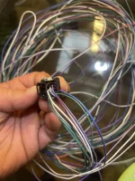
 Does anyone have the wire harness pin layout for a 2022 Ford F150 raptor ? I’m trying to build my own wire harness. I’ve allocated a 2022 f150 raptor overhead console and I just ordered a connector for plugging into the upfitters above the console as well as the pins themselves but I’m having a hell of a time trying to figure out which pin controls what exactly
  any help anyone can provide would be greatly appreciated

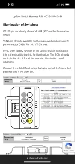
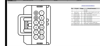
 I can’t figure out if this is true or not. Someone said this is the correct diagram. Screenshot below
  I even found someone on eBay selling open for $25 bucks but the wire colors don’t match up