What's new

Aux switch wiring?

When wiring a solenoid to an aux switch to apply power to a winch, the amp rating of the switch doesn't matter right? I should be good to wire it to any of them?
 
When wiring a solenoid to an aux switch to apply power to a winch, the amp rating of the switch doesn't matter right? I should be good to wire it to any of them?
Correct. So long as the switch has the minimum current and voltage.
 
When wiring a solenoid to an aux switch to apply power to a winch, the amp rating of the switch doesn't matter right? I should be good to wire it to any of them?
Yah like Yeti said, if your just triggering a selonoid I don't even think you will pull 5A so you could go to any of them but if it was me I'd go to the smallest ones and not waste any of the larger relayed circuits. 👍👌
 
When wiring a solenoid to an aux switch to apply power to a winch, the amp rating of the switch doesn't matter right? I should be good to wire it to any of them?
Just curious, are you installing a line interrupt solenoid or making the overhead switches the controls?
 
Got the winch wired up tonight. It works, but there is a short to ground somewhere. One of the bolts that mounts the winch to the bumper would spark when I hit the button to wind it in or out. Also the solenoid was really hot after winding in about a foot of line. Not sure if that is due to the short to ground or the solenoid not being up to the task. My understanding is that the solenoid is grounded through the mounting bolt to the frame. If it wasn't making good enough contact there could that be causing the spark on the bumper?
 
Got the winch wired up tonight. It works, but there is a short to ground somewhere. One of the bolts that mounts the winch to the bumper would spark when I hit the button to wind it in or out. Also the solenoid was really hot after winding in about a foot of line. Not sure if that is due to the short to ground or the solenoid not being up to the task. My understanding is that the solenoid is grounded through the mounting bolt to the frame. If it wasn't making good enough contact there could that be causing the spark on the bumper?
Found the issue with the sparking. Skipped a step when hooking it all up and missed an extra ground cable. Looks like it's grounding through the winch frame to the bumper right now lol. Should be an easy fix.
 
Got the winch wired up tonight. It works, but there is a short to ground somewhere. One of the bolts that mounts the winch to the bumper would spark when I hit the button to wind it in or out. Also the solenoid was really hot after winding in about a foot of line. Not sure if that is due to the short to ground or the solenoid not being up to the task. My understanding is that the solenoid is grounded through the mounting bolt to the frame. If it wasn't making good enough contact there could that be causing the spark on the bumper?
Disconnect everything. My solenoid is ground isolated as I think many are. Check all the wiring for bare wire, maybe something took a nick somewhere. It will probably be between the solenoid and the winch
 
Did anyone else have trouble getting the A bundle out? I could hardly get the bundle to a point where I could actually work with it and I am not sure if it’s taped back under there somewhere I can’t see. I nearly cut my hands trying to get the aux 1 cable out for me to connect to it. Just curious if there was just my truck or if mine is a one off. Thanks.
 
Did anyone else have trouble getting the A bundle out? I could hardly get the bundle to a point where I could actually work with it and I am not sure if it’s taped back under there somewhere I can’t see. I nearly cut my hands trying to get the aux 1 cable out for me to connect to it. Just curious if there was just my truck or if mine is a one off. Thanks.
I have not tried to wire mine yet but.......I did unscrew my wheel well liner in fall to tap in to the parking light circut for my gill lights. I had to pull down the wheel well liner to get in there and you can actually get at the upfitter wires pretty easily and pull them down outside the fender to wire stuff in. I am not sure if this is easier then just removing the battery or not but you could try it????
 
Did anyone else have trouble getting the A bundle out? I could hardly get the bundle to a point where I could actually work with it and I am not sure if it’s taped back under there somewhere I can’t see. I nearly cut my hands trying to get the aux 1 cable out for me to connect to it. Just curious if there was just my truck or if mine is a one off. Thanks.
Can confirm that the bundle does not have much cable to work with. I'm not sure your experience was the same as mine, but I can tell you that I wish they gave me 6-10 inches more cable. Insert "that's what she said" joke here.

Although it was really tight and I had to make my connections really close to the side of the engine bay, I was still able to manage some decent connections and stowed it away nicely. But it definitely was not ideal. I contemplated making a harness to extend all the cables out for better access. But in the end I just connected to the bundle and stowed the connections away where the bundle was originally. It works. It could be neater.
 
Perfect! Thanks!

So everything is run to the fuse box which is sufficient. It would be nice if wires were pre-run several places like the bronco. But I don’t mind running wire, and still have not decided what I will use the switches for.

Some initial ideas are light bar behind grill and recessed floods in rear bumper.

Anyone else have plans or ideas for the aux switches?
il_1140xN.3989640070_441z.jpg

For James Bond wannabes?
 
Had some loud horns installed (I have to drive in Miami and Broward sometimes). They used the power from the third upfitter switch on the power side of two relays, with a tap from the horn on the 2 relay actuation sides. Not real happy with it as it works intermittently and blows fuses. I know enough about electrical to get in trouble and thought I could solve the problem by adding a third relay which would allow me to tap the battery for the power side of the relays. Sketch below. Any reason this will not work? Upfitter switch closes solenoid sending battery power to two downstream relays, which are triggered by the horn tap. Does anybody know how much power these solenoids typically draw on the actuation (not power) side?
 

Attachments

  • Relays copy.webp
    Relays copy.webp
    38.6 KB · Views: 74
Last edited:
Had some loud horns installed (I have to drive in Miami and Broward sometimes). They used the power from the third upfitter switch on the power side of two relays, with a tap from the horn on the 2 relay actuation sides. Not real happy with it as it works intermittently and blows fuses. I know enough about electrical to get in trouble and thought I could solve the problem by adding a third relay which would allow me to tap the battery for the power side of the solenoids. Sketch below. Any reason this will not work? Upfitter switch closes solenoid sending battery power to two downstream solenoids, triggered by the horn tap. Does anybody know how much power these solenoids typically draw on the actuation (not power) side?
Pm the horn and compressor specs. Or post the kit you have
 
HS Mega Blast air horn. Attached is all I got for paperwork. Relays are 4 point, not 5.
 

Attachments

  • IMG_1233 (1).webp
    IMG_1233 (1).webp
    304.4 KB · Views: 51
Last edited:
HS Mega Blast air horn. Attached is all I got for paperwork. Relays are 4 point, not 5.
Two things without looking too deep.
1. A 40 amp relay and switch feeding a 60 amp circuit.
2. The instructions show a ground side switch. Not sure why but it may be important.
60 amp relay and 60 amp fuse on the ground side may be the answer
see what rating the switch that came with it is.
 
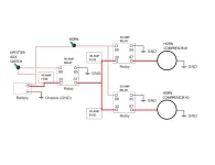
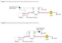
Thanks for the input. My sketch above shows the proposed alignment. Currently power is coming from a 15 Amp upfitter switch power source split to the power side of the two relays/compressors on the right, and it does drive the horns sometimes (very lame by the installer). Yeah, might be better to find a 60 amp relay. Worst case it will blow the 40 amp fuse, and I kind of doubt these small compressors will draw 30 amps (very large low-loss cable going to the compressors). I have a clamp meter which can measure DC amps so I can check the actual current draw. My biggest concern is the logic of using one relay to energize the power side of the two downstream relays, thought I can't see any issue aside from the fact that if the compressors really draw 30 amps each, it will blow the upstream fuse / relay. At first I wanted to just have the horn to the upfitter switch, but the installer thought better to be connected to the horn circuit to avoid accidental actuation. For these relays, supposedly hot side or ground side actuation shouldn't matter according to the sketch here for normally open relays. The kit didn't come with a switch. Maybe with real power coming to the compressors the horns will be louder, but even with only 7.5 amps going to each they are really loud. Oh I corrected my original question as I used the word solenoid instead of relay. There are no solenoids.
 

Attachments

  • NO Relays.webp
    NO Relays.webp
    37.3 KB · Views: 53

Recent Discussions

Back
Top