What's new

Aux switch wiring?

I thin either 6 or 5 and 6 can bet active if you set the proper switch in the engine fuse panel

On the Superdutys you can make 5 and 6 constantly hot by moving the fuse in the panel. I have not looked at the Tremor yet. I think the switches are lame as can be after owning Switch-Pro's.
 
On the Superdutys you can make 5 and 6 constantly hot by moving the fuse in the panel. I have not looked at the Tremor yet. I think the switches are lame as can be after owning Switch-Pro's.
I'm using my switchpros for my camper house power and the aux switches for less used stuff
 
On the Superdutys you can make 5 and 6 constantly hot by moving the fuse in the panel. I have not looked at the Tremor yet. I think the switches are lame as can be after owning Switch-Pro's.
Can confirm that we can’t get any constant power out of the aux switches. I looked into it when I put my reverse lights on.

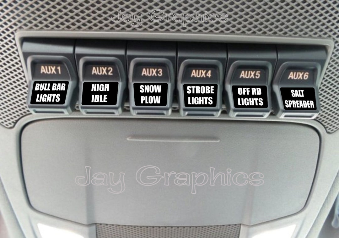
On another kinda related note has anyone had any success with aux switch labeling? I have a cheap label maker but always looking for better ideas.
 
Can confirm that we can’t get any constant power out of the aux switches. I looked into it when I put my reverse lights on.

On another kinda related note has anyone had any success with aux switch labeling? I have a cheap label maker but always looking for better ideas.
I was just thinking about that as I'm heading home through Kansas...

I did see something about custom labels for them. Otherwise I'll get the black tape with white lettering
 
Can confirm that we can’t get any constant power out of the aux switches. I looked into it when I put my reverse lights on.

On another kinda related note has anyone had any success with aux switch labeling? I have a cheap label maker but always looking for better ideas.
 
Research tells me this should work. Anyone confirm?

Rough draft using Greenshot to edit. Should get the point across though.

1661047262113.webp
 
Depending on the load, you may want to feed the device with another relay (2) and a fused positive through relay 2. If the drls or headlights and device are more than the feed fuse, it'll pop
There are 2 input nc/closed/closed/open relays you would feed from a fused battery connection.
 
I would only be running the fender lights off this. I would imagine a simple 5 amp inline fuse would work.

Perhaps something I'm misunderstanding?
 
I would only be running the fender lights off this. I would imagine a simple 5 amp inline fuse would work.

Perhaps something I'm misunderstanding?
Possibly. In your diagram, the power source is the drl/headlights lead you're tapping in to. The aux switch is the activator. Double check your relay that your aux power is feeding the device and you should be good.

Normally you would expect the big power to power the device(which is what I was talking about) In your case, the drl is the switch and the aux switch is the power to the device.

Got it. I figured since both the Aux 1 is providing 12v+ and the DRL is providing 12v+, either one would be find as the trigger technically.

I should have erased battery in that diagram because the "battery" is in this case the DRL. Does that still make sense? Just making sure.
 
Got it. I figured since both the Aux 1 is providing 12v+ and the DRL is providing 12v+, either one would be find as the trigger technically.

I should have erased battery in that diagram because the "battery" is in this case the DRL. Does that still make sense? Just making sure.
yup, sure does. Yeah, I already ignored the battery :). My only thought on which is the feed is that I wouldn't want to add an additional load (more lights) in to a critical circuit (headlights).

So yeah, you've got this.
 
Does anyone know of a reasonable guide to setting up aux switch accessories? I would love something that had recommended products with links to them... its overwhelming to try and figure out what is Amazon garbage and what is actually the best way to do something.
 
Found a little sumthin, sumthin, that might help some people wire the switches a little easier. I am going to run two of them and will do a full write up in my build thread and maybe even a separate post. 4 place solid state relay box. 1-4 AWG input and 4-8 AWG outputs. 1- 40 amp spot and 4- 20 amp spots with both positive and negative triggers.

IMG_2334.webp


IMG_2340.webp


IMG_2342.webp
 
Found a little sumthin, sumthin, that might help some people wire the switches a little easier. I am going to run two of them and will do a full write up in my build thread and maybe even a separate post. 4 place solid state relay box. 1-4 AWG input and 4-8 AWG outputs. 1- 40 amp spot and 4- 20 amp spots with both positive and negative triggers.

View attachment 6288

View attachment 6289


View attachment 6290
I would love to see a full write up of this!
 
Agreed. I can't wait for that! Thanks for sharing.
 
Found a little sumthin, sumthin, that might help some people wire the switches a little easier. I am going to run two of them and will do a full write up in my build thread and maybe even a separate post. 4 place solid state relay box. 1-4 AWG input and 4-8 AWG outputs. 1- 40 amp spot and 4- 20 amp spots with both positive and negative triggers.

View attachment 6288

View attachment 6289


View attachment 6290
Yeah man. That is pretty slick. Not sure I can use it for my current setup but may be worth buying a couple
 
Yeah man. That is pretty slick. Not sure I can use it for my current setup but may be worth buying a couple
The big advantage to using this is the fact you can instantly upgrade the 5 and 10 amp up fitter switches to 20's and a 40. With just one you would end up with 1-40 , 3-20's and 2-15 amp circuits. 15 amp being the largest stock relays left alone. Pretty much plug and play type install anyone can figure out.
 

Recent Discussions

Back
Top